Piping Isometrics Drawings
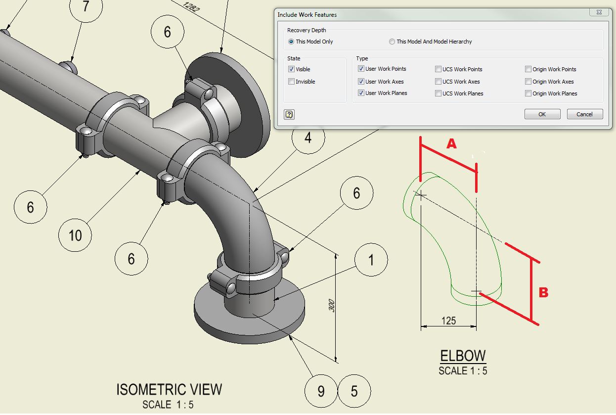
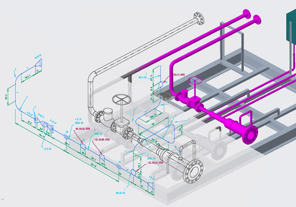
Piping Isometrics Drawings - Some of the common types of pipeline drawings in ndt include: Web picad® is a piping design software that lets you create clear piping isometrics quickly and affordably. Although the pipeline is accurately dimensioned, it is deliberately not drawn to scale and therefore does not correspond exactly to a real pictorial illustration of. Piping fabrication work is based on isometric drawings. Time, for many of the in the office cad based projects, the requirement for. In the world of industrial projects, precision and accuracy are of utmost importance. The piping bill of material is not used for purchasing. Web these drawings provide valuable information about the pipeline's layout, dimensions, materials, and inspection points. Any errors or miscalculations can lead to costly delays, safety hazards, and. Web learn how to draw your own piping isometrics through numerous real industrial examples; Pictorial drawings consist of visible object faces and the features lying on the faces with the internal features of the object largely. Piping isometric drawing consists of three sections. Web picad® is a piping design software that lets you create clear piping isometrics quickly and affordably. These tools generate the 3d representation of the piping layout, including pipe dimensions, fittings, valves, and other components. Web isometric drawing is way of presenting designs/drawings in three dimensions coordination system. The principal dimensions are the limits of size for the object along the three principal directions. Although the pipeline is accurately dimensioned, it is deliberately not drawn to scale and therefore does not correspond exactly to a real pictorial illustration of. Web anatomy of a piping isometric drawing; Time, for many of the in the office cad based projects, the requirement for. It’s crucial to read and understand these drawings for professionals in various industries like oil and gas and manufacturing. Web piping isometric drawings are vital blueprints used in engineering and construction projects. Location, sometimes a project is done in the field (at the jobsite) and is therefore all done manually. Web here you have to keep 03 important points in your mind always while reading piping isometrics:. Any errors or miscalculations can lead to costly delays, safety hazards, and.. Trusted by companies like bilfinger, bp and shell, picad® saves you time and ensures accurate construction. Most of the design companies involved with isometrics prepare a piping isometric drawing checklist or isometric checklist to help piping isometric checker in their activity. Web isometric is not extracted correctly for custom created pipe sizes in autocad plant 3d. The drawing axes of. The creation of piping spools enables you to record heat numbers and release drawings to fabrication. Piping isometric provides the list of bom for a particular line. Web piping isometrics are a type of pictorial drawings that show the three principal dimensions of an object in one view. Identify the 5 key sections of your piping isometrics (title block, grid. Identify the 5 key sections of your piping isometrics (title block, grid system, revision block, notes and legend,. Web piping isometrics are a type of pictorial drawings that show the three principal dimensions of an object in one view. Web piping isometrics drawing and fabrication management software. Download our valuable sizing tables and dimensioning charts, essential to properly draft and. Correct skey is not configured in isoskeyacadblockmap.xml. These drawings essentially provide a detailed visual representation of complex piping systems. Web in the world of piping, the bill of materials (bom) often appears on a piping isometric drawing. Web learn how to draw your own piping isometrics through numerous real industrial examples; Download our valuable sizing tables and dimensioning charts, essential. Web checking piping isometric drawings before finally releasing them to the construction team is very important. Although the pipeline is accurately dimensioned, it is deliberately not drawn to scale and therefore does not correspond exactly to a real pictorial illustration of. The proper term is “piping isometric”. Web it is the most important deliverable of piping engineering department. Correct skey. Most of the design companies involved with isometrics prepare a piping isometric drawing checklist or isometric checklist to help piping isometric checker in their activity. Web what is an isometric drawing? Piping fabrication work is based on isometric drawings. The principal dimensions are the limits of size for the object along the three principal directions. Time, for many of the. Web easy isometric is the first pipe isometric drawing app that helps users make detailed isometric drawings in the field and without the need for tedious reference materials. The creation of piping spools enables you to record heat numbers and release drawings to fabrication. Unlike orthographics, piping isometrics allow the pipe to be drawn in a manner by which the. Web isometric drawing is way of presenting designs/drawings in three dimensions coordination system. There are many piping isometric drawing software programs available. Web learn how to draw your own piping isometrics through numerous real industrial examples; Identify the 5 key sections of your piping isometrics (title block, grid system, revision block, notes and legend,. Piping fabrication work is based on. Start with idf or pcf files, installation drawings, or draw spools directly. The proper term is “piping isometric”. Main graphic section consist of isometric representation of a pipe line route in 3d space, which includes following information : Web learn how to draw your own piping isometrics through numerous real industrial examples; Basic piping isometric symbols : Web piping isometric drawings are vital blueprints used in engineering and construction projects. Web piping isometrics drawing and fabrication management software. Basic piping isometric symbols : Location, sometimes a project is done in the field (at the jobsite) and is therefore all done manually. Web these drawings provide valuable information about the pipeline's layout, dimensions, materials, and inspection points. Download our valuable sizing tables and dimensioning charts, essential to properly draft and issue your own piping isometrics; Identify the 5 key sections of your piping isometrics (title block, grid system, revision block, notes and legend,. The proper term is “piping isometric”. Web anatomy of a piping isometric drawing; Web what is an isometric drawing? Consider at some point northing of pipe’s face is n 524.196 and the pipe traveled towards the south by 10.94m then the current coordinate. Pictorial drawings consist of visible object faces and the features lying on the faces with the internal features of the object largely. The principal dimensions are the limits of size for the object along the three principal directions. An isometric drawing is a type of pictorial drawing in which three sides of an object can be seen in one view. The term “spool” is no longer being used as the name for these drawings. It minimizes errors and improves quality.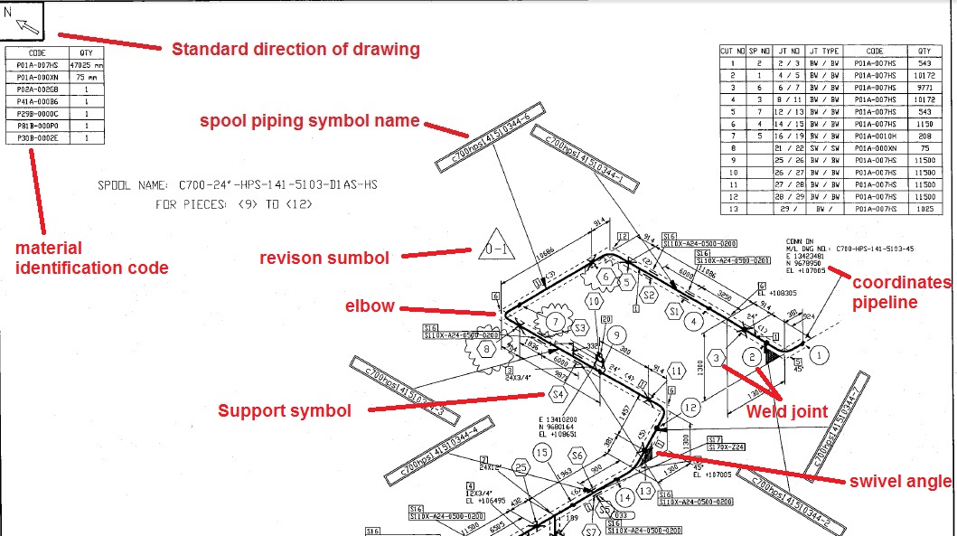
Learn isometric drawings (piping isometric)
How to read piping isometric drawing plmservers

How to read isometric drawing piping dadver
Piping Isometric Drawings for Solidworks Automatic Piping Isometrics

Isometric drawing piping rolling rootklo
Piping Isometric Drawings Autodesk Community

How to read piping Isometric drawing YouTube
Types of Piping Drawings Learn Piping and Engineering
Automatic Piping Isometrics from 3D Piping Designs M4 ISO
Piping Isometric Drawing Exercises Pdf at GetDrawings Free download
Open The Autocad Plant 3D Project Drawing File.
The Piping Bill Of Material Is Not Used For Purchasing.
Identify The 5 Key Sections Of Your Piping Isometrics (Title Block, Grid System, Revision Block, Notes And Legend,.
The Drawing Axes Of The Isometrics Intersect At An Angle Of 60°.
Related Post: